[h=1]Casing Seat Selection – How To Select Casing Setting Depth[/h]
From the previous article, you’ve learnt about overall of casing design process and in this article we are going to discuss about how to select casing setting depth. The selection of casing string and setting depth is based on formation pore pressure and fracture gradient of the well.


Figure 4 – Bottom Up Design Step#2


From the previous article, you’ve learnt about overall of casing design process and in this article we are going to discuss about how to select casing setting depth. The selection of casing string and setting depth is based on formation pore pressure and fracture gradient of the well.
For the casing setting depth determination, pore pressure and fracture gradient are normally described in PPG (Figure 1).
Figure 1 – Pore Pressure and Fracture Pressure Plot
The solid lines in the chart are not accounted for safety factor; therefore, for the first step of casing seat design, safety margin must be applied. For this example, we will add 0.3 ppg for safety for both pore pressure and fracture gradient (Figure 2). You need to add the safety factor into formation pressure and subtract it from the fracture gradient. What’s more, the safety factor value may depends on where you work and how much confident in your data.
Figure 2 – Pore Pressure and Fracture Pressure Plot with Safety Margin
The dashed lines are design range which will be used for the design. There are two ways to determine casing setting depths which are bottom-up and top-down method.
Bottom Up Casing Design
This design will start from the bottom of the well up to surface and the setting depths are designed within the safety factor limits (dotted lines). Starting at the bottom (formation pressure dashed line – Point A), draw a vertical line upward to fracture pressure dashed line – Point B (Figure 3). Casing should be set from 4,500’ TVD to 12,000’ TVD because you can reach TD (12,000’ TVD) with highest equivalent mud weight and you will not break the formation at shallow depth (4,500 TVD). We will apply this same concept to another string.
Figure 3 – Bottom Up Design Step#1
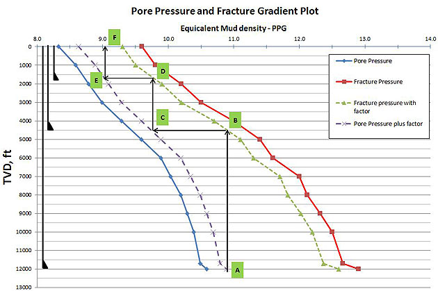
The next casing string is determined by drawing a horizontal line from Point B to intersect the pore pressure dashed line at Point C. Then draw a vertical line from Point C to the fracture gradient dashed line at Point D (Figure 4). The Casing must be set from 1,800’ TVD to 4,500’ TVD.
Figure 4 – Bottom Up Design Step#2
With the same idea, the next casing string is determined by drawing a horizontal line from Point D to Point E and a vertical line from Point E to Point F (Figure 5). The Casing must be set from surface to 1,800’ TVD.
Figure 5 – Bottom Up Design Step#3
Based on the bottom up design concept, we will need to have 3 strings of casing set at 1800’ TVD, 4500’ TVD and 12,000 TVD (Figure 6).
Figure 6 – Bottom Up Design Final
From the example, you can see how the bottom up casing design process is done. If you have the different pore pressure/fracture gradient, you can repeat the process for other casing strings until you reach surface casing.
Top Down Casing Design
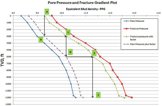
This design will start from the surface of the well down to the bottom and the setting depths are designed within the safety factor limits (dotted lines). We start by drawing the vertical line from the facture gradient dashed line (point A) down to pore pressure dashed line (point B). See Figure 7. The first casing should be set from surface to 3,000’ TVD.
Figure 7 – Top Down Design Step#1
Next, draw the horizontal line from Point B to Point C located in the fracture dashed line curve. Then draw the vertical line from Point C to intersect the formation pressure dashed line curve at Point D. This is the section casing string which should be set from 3,000’ TVD to 6,000’ TVD (Figure 8).
Figure 8 – Top Down Design Step#2
Applying the same concept to the next string, draw the horizontal line from Point D to intersect the fracture gradient with safety factor chart at Point E and draw the vertical line from Point E to the target depth at Point F. The last casing string should be set from 6,000’ TVD to 12,000’ TVD (Figure 9).
Figure 9 – Top Down Design Step#3
Based on the tow down design concept, we will need to have 3 strings of casing set at 3,000’ TVD, 6,000’ TVD and 12,000 TVD (Figure 10).
Figure 10 – Top Down Design Final
From the example, you can see how the top down casing design process is done. You can repeat the same process to determine the setting depth based on your fracture and pressure plot.
by DrillingFormulas.Com on June 2, 2014
reference book: applied drilling engineering
by DrillingFormulas.Com on June 2, 2014
reference book: applied drilling engineering